(This post is based on a LumberJocks.com forum thread.)
After completing my dust collection system installation, I turned to my air cleaner, the Delta 50-875. I had decided to install it just above my table saw — about 2/3rd’s of the way along the wall, where the intake would be in line with the front door and the outfeed inline with the ceiling mounted vent fan. After reading “Woodshop Dust Control” this seemed like the ideal placement and this location had the added benefit of not obscuring any usable wall space — which is at a premium in my small shop.
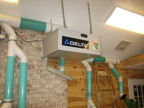
An Awkward Arrangement
One of the selling points of this unit is the built-in infrared remote control that allows you to install it out of reach and control it from below. The problem is that the remote sensor is in the back of the unit. While the unit location is ideal for air flow, it’s rather awkward for IR control as I’d need to walk around to the back of the unit, and to a “far” corner of the shop, to turn it on/off. I’ve always thought that what I really wanted to do was to control it with a switched outlet. The problem with that scenario is that the control panel built into the unit is solid state and doesn’t “remember” the settings when you unplug the unit. That is, if you turn it on and then switch off the outlet it’s plugged into, when you switch the outlet back on, the air cleaner will remain “off” until you again manually press the “on” key on the unit or the remote control.
So, there was no way to make this happen…or was there? I reasoned that since it’s just an electric motor and a control panel, certainly there would be a way to re-wire the unit, bypassing the built-in solid-state controls so that I could hook to a switched outlet.
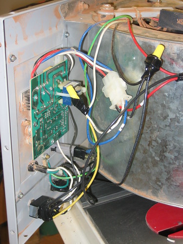
Exploration
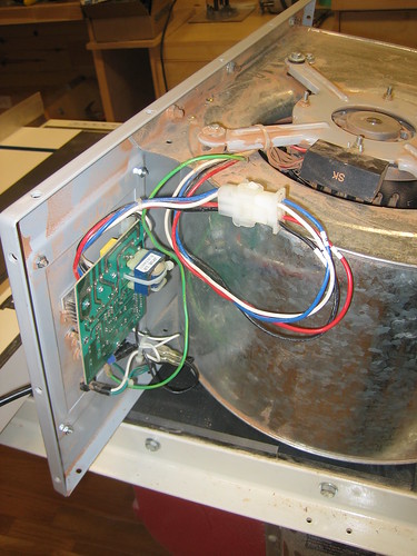
The air cleaner itself is pretty basic. It’s a rectangular metal box with a blower motor/fan in a housing, and a control panel. The motor and control panel are both mounted on the back panel which is simply screwed into the metal box. Once the backpanel assembly, including the blower was removed, I began the process of working out exactly what needed to be done to re-wire the motor. Fortunately, the motor wiring connects to wires from the controller through a nylon connector that, once unplugged provided an easy means of measuring various voltages and resistance. As I knew nothing about wiring AC motors, I began the process with a google search…many of them. Unfortunately, none provided me with anything that I could really use to definitively determine how this motor worked. In fact, I was left with more questions than I’d had originally…who knew there were so many types of AC motors! Initially, as there were 3 colored wires (Red, Blue and Black) and one White (clearly “common”), I assumed there were 3 windings and each color represented one of the 3 speeds that the unit boasts. Based on what I’d read, however, I was now concerned that the large-ish capacitor on the red wire indicated that I might have a “capacitor start” motor which would require something more complicated than simply applying voltage to one of the wires. Perhaps an electrical engineer, at this point, would have provided me a definitive way to check this out…but there weren’t any in my shop, so I tried a different tack.
I reasoned that the best way to reverse engineer this setup was to hook up each of the colored wires in turn to my volt meter — using white for common — and turn the unit on, cycle through the various speed settings and note the voltages. This did the trick. Here are the measured results:
| wire | slow | medium | fast |
|---|---|---|---|
| RED | 121V | 9V | 9V |
| BLUE | 9V | 121V | 9V |
| BLACK | 14V | 14V | 121V |
Clearly this was going to be as straight-forward as I had first hoped! Red = slow, blue = medium and black = fast. That’s all there was to it!
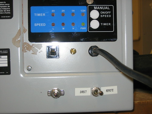
Let the hacking begin…

Now I was ready to start. In thinking through exactly how I wanted to wire this up, I realized that I might want to have the ability to change the speed at some point without opening the unit up. I also figured it would be pretty simple to install a switch that would basically allow me to “undo” this hack and use the unit as nature, and the Chinese factory had intended without having to un-hang and re-open the unit. The solution was a couple toggle switches. Since there’s an Ace hardware store right up the street from my office, I decided to stop by at lunch and see what they had. I was looking for a SP3T rotary switch that would allow me to cycle through all three speeds — but the only one they had was rated at 4A max. The fuse mounted in the control panel is rated at 5A, so I figured this switch wouldn’t do. The next closest was a SPDT switch, center off — and two speeds seemed “close enough.” For the “hack bypass” switch, I got a DPDT. While it seemed like it should be sufficient to switch only the “hot” wire, since I was going to essentially be supplying power to the output of the controller when using the hack (see drawing), I was concerned that a closed common connection might allow a circuit to complete and result in “who knows what”(tm) happening. So, I decided the safest thing to do would be to simply switch both common and hot.
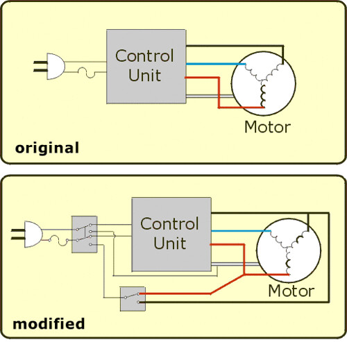
The plan
Here’s a basic drawing of what was done:
Moving forward
So the whole point of this modification was to allow me to control the unit by a switched outlet. The switched outlet is managed by an Insteon SwitchLinc which will allow for event-driven activation, such as turning on and off automatically with tools and/or the dust collection unit and wireless RF remote control via an X10 keychain remote. I’ll be refining the programming over the coming weeks/months.