Isolation Milling a Custom PC Board

This entry is part 1 of 1 in the series Foosball Scorekeeper

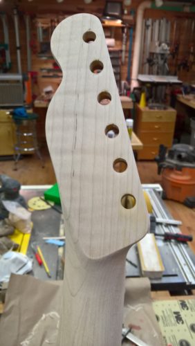
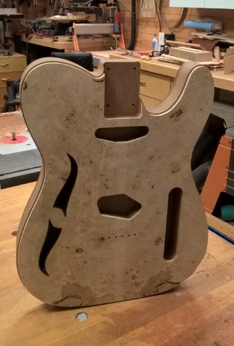
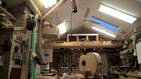
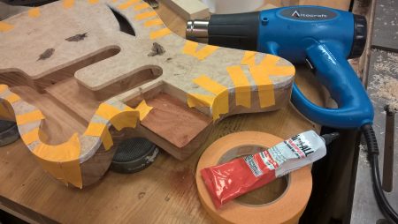
While the finish was curing on my latest guitar project … and while I worked out how to fix some issues with inadvertant overspray … I turned my attention to another interest: electronics.

The kids and I have been playing around lately with Arduino. OK, well mostly me, but I’ve managed to catch the interest of my 10 year old son, with whom I prototyped a rudimentary “guitar tuner” using a nano, piezo, and several push buttons. My 11 year old daughter’s caught the bug as well, or should I say the mouse as we’ve been working on an analog project “Mousey the Junkbot,” though thus far without much success.

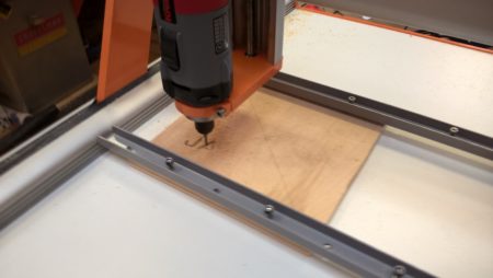
In any case, I’ve been itching to try out PCB engraving – or “isolation milling” on the CNC machine. If you’re not familiar, this is basically the process of creating a circuit board from raw copper clad board by removing the negative bits between the traces you want, thereby isolating the lines you need from one another. This may be done on a CNC machine with a very fine engraving bit – many sold specifically for this purpose.

Being a newbie to PCB design and fabrication, I naturally turned to the Internet for advice. I found numerous options and tried several of them. In the end I managed to cut a few good boards, with some headaches and false starts along the way.

Fritzing (http://fritzing.org)

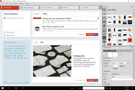
Fritzing main screen

This is one of the first programs I discovered while learning Arduino. It’s free and boasts an attractive UI. My initial design for the circuit used a 2-digit 7-segment display, which wasn’t available in the Fritzing parts inventory. I attempted to create one of my own and found the process frustrating. I also experienced some UI issues with the parts library dissappearing and overall sluggish program response. I was also hoping to find a way to simulate my circuit so I could work on it while I was on vacation or simply commuting between work and home. And so, I kept searching.


Circuits.io (http://circuits.io)
Next I stumbled upon this pretty amazing site by Autodesk. Here you can virtually prototype and simulate your circuit designs. It even allows users to develop Arduino code that executes in the simulated environment. I was able to build my prototype circuit, test out the code and ensure I wasn’t going to blow things up. While this all works well, there are still some issues. First, the site is sloooooooow. I realize it’s doing a lot, but at times it’s completely unusable, especially when I’m mobile. The inventory of available parts is also fairly limited. Considering the fact that every part in the system needs to be coded to work within a simulation, this isn’t surprising. However, I found it odd that there was a common anode 7-segment display, but not a corresponding common cathode version…which is basically the same thing but in reverse. This was very inconvenient as I had common cathode displays on hand and wasn’t about to purchase a replacement just because it wasn’t simulatable within circuits.io. I wound up designing and testing the circuit on the website using the common anode version of the part, and then cloning the project and reconnecting the common pin to ground in order to design the PCB board. I also ran into a few odd bugs – one of which necessitated deleting the project at one point and starting over. My posts to the support site to this day have remained unacknowledged. Sigh.

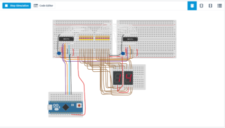
Simulating a 2-digit 7-segment LED circuit

That said, I did manage to design a PCB board, export the Gerber files for it, and upload these to OSH Park. I immediately ordered 3 boards from there for <$20 and, while awaiting these, continued my tool search to see if I could find a tool I could use to mill my own boards.

There is an option on the circuits.io site to “Export Eagle Board,” however it never actually worked for me. No matter which design I used (and I tried some very basic ones), the site gave me an error saying it was unable to connect to the service. Clearly this feature is broken and there doesn’t seem to be any urgency to supporting this site. I searched around instead for a way to convert the downloaded Gerber files into usable CNC gcode. For this I found pcb2gcode and pcb2codeGUI.

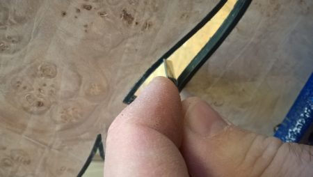
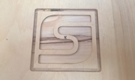
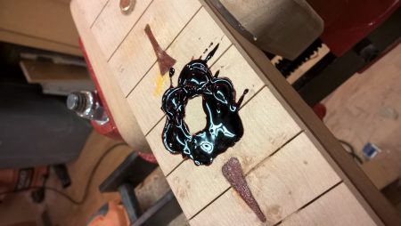
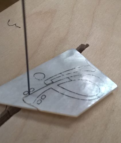
My first try looked very pretty but suffered from some incomplete traces. I was also struck by just how tiny it was! Looking at it on screen for a few days I never got the sense of just how tiny these lines were. But once cut into a PCB I required magnifiers to verify the traces. I had set the depth a bit too shallow and hadn’t compensated for variations in thickness/level of the board on the CNC. I tweaked the gcode Z value and tried again. This time the board looked good, but the traces were too narrow in spots and there were incomplete routes. I also wasn’t sure how I could solder these connections. The traces passed so close to the connection points that I didn’t feel I could keep my solder work from shorting some of them out. I tested this out anyway and decided I really did need to make myself some more room.

After several attempts at getting this right using circuits.io and pcb2gcode, I decided I should invest some time reviewing and hopefully learning “Eagle.”

Eagle (https://www.autodesk.com/products/eagle/overview)
Another Autodesk product/acquisition, Eagle is the old dog in EDA (Electronic Design Automation) software. It was developed in the late 80’s and the UI hasn’t apparently seen many changes since. Wherever I looked around for info on circuit design, Eagle kept appearing. Clearly this was one of – if not the – industry-standard EDA tool available today. It took a bit to get a feel for the rather clunkly and clumsy UI, but once I managed to get the hang of it…well, so I still haven’t totally gotten the hang of it, but I am many times better with it now than when I initially picked it up. It really would benefit from a major UI overhaul by Autodesk, though I imagine they’d need to maintain some degree of backward compatibility for those with years – if not decades – of practice with the existing interface.

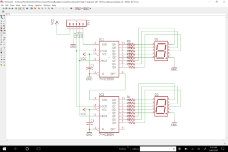
Circuit design for 2-digit display module

I really liked the schematics I was able to produce with this tool. There are also libraries avialable for just about any part you could want. Many of them contributed by users and posted to Github. Most of the “maker” retailers have made their components freely avaialble as Eagle libraries as well. I drew up the schematic based on the simluation circuit from circuits.io (so I knew it would work) and switched to the PCB view.

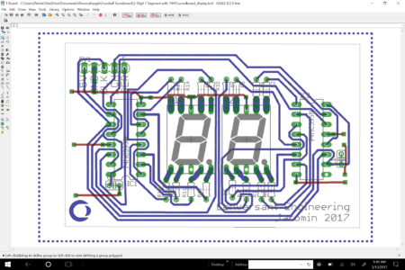
PCB design for 2-digit display

I played a bit with the autorouter, which helped me visualize some routing options. However, in the end I wound up routing nearly all of my own traces. There are some idiocyncrasies with routing that continue to bug me – like how sometimes it wants to snap to odd paths when there’s definitely enough clearance to go the more direct route. I’ve wound up fighting the tool on more than one ocassion. After a few scrapped designs, I was able to create a pretty decent looking board.

PCB-GCode ULP

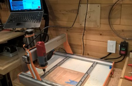
The next step was to turn this into usable G-code for my CNC. The plugin that kept turning up was “pcb-gcode“. This ULP (user level program) runs within Eagle and provides a GUI that you can work with to produce g-code appropriate for your particular machine. After some toying around, I managed to export some gcode that looked pretty good in the UCCNC software used by my stepcraft CNC machine.

At this point I’m on my 5th or so board and have been getting fairly consistent results with trace widths of 1.27mm and a z-depth of .03mm. It’s still somewhat challenging to solder some of the connections due to the proximity of the traces, but with some patience I’ve been able to get them to work properly.

So far I’ve assembled 4 2-digit boards – 3 using the OSHPark factory boards and 1 with my own shop-milled PCB. I’ve also successfully milled the main controller board and have tested the final assembly with a simple counter program. It works!

https://www.instagram.com/p/BS6nS7pBkH0/

Next up is building the remote scoring units with increment and decrement buttons, as well as an interface for a future automatic goal sensor.

Facebook Comments
Categories: Electronics | Leave a comment

Hands-on with the Shaper Origin!

Heading to the Mission district

Prototype

More prototypes

Later versions

Demonstration of the Shaper Origin

Design lead Matty Martin providing demonstrations and usage tips to visitors.

Shaper HQ in SF

The unit I was able to try out.

When I was first searching for a CNC to add to my shop, I ran across an odd tool called the Shaper Origin. The tool was in essence a self-correcting router that works like a hand-held CNC machine. I spent some time watching the videos on their site and reading through the blog. It was a novel idea, though it wasn’t quite ready to ship (as I write the the first batch is slated to ship Fall 2017) and not really what I wanted/needed for guitar work. Still, it seemed absolutely incredible. Unbelievable really. Could such a thing really work?

These weren’t the sort of directions I was looking for, but I decided it best not ignore the advice of a beat cop.


Fast-forward to late February when I receive an email invitation (I had signed up on their mailing list, natch!) to come see a “private demo” and get a chance to actually try out the tool in their San Francisco HQ. Because I live in Chicago, this normally would have been filed away with a sigh. However, as luck would have it, I was signed up to attend the Strata + Hadoop World conference in San Jose that same week. To top it off, the demo was scheduled for 6pm on the last day of the conference (which ended by 5pm).

Done deal…sign me up!

On Thursday, March 16th, I rushed out of the conference a bit early to catch one of the evening express Caltrain’s up north to SF. Following advice I’d requested and recieved via email from the fine folks at Shaper, I transferred to a BART at Millbrae, taking that train up to 16th Street Mission station. I emerged from the BART via a fairly formidible flight of stairs, and immediately noticed a pair of SF’s finest watching over the active plaza.

“Can you tell me where Shotwell is?,” I asked. The initial look on their faces left me a bit uneasy. “What’s on Shotwell?” the male officer queried, shooting a sideways glance at his female partner. “Umm…a tool company” I replied.

Pointing down the street over my right shoulder, he proceeds to inform me it’s a couple blocks “that way” and that I should be sure to keep both straps of my backpack over my shoulders and not to walk around with my phone in my hand. These weren’t the sort of directions I was looking for, but I decided it best not ignore the advice of a beat cop.

Shotwell street – this block anyway – is basically industrial and not really intimidating. There’re typical buildings and a fenced-in parking lot across the street from Shaper HQ. Following a simple note taped to the door at 274 Shotwell, I walked on a bit until coming upon a small open garage bay. Inside were a handful of folks milling about (it was a bit before the 6pm start time – at least I think it was as I didn’t dare take my phone out of my pocket to look.)

I quickly slide the machine to the side to get a closer look at the point where the start and end of the circle met. My eyes and fingers couldn’t find any variation.


The shop is small and very cool. Next to a couple metal buckets of beer sat a table hosting the history of the Shaper Origin from initial prototype to its current inception. In the middle of the shop a live online demo was taking place. I watched the tail end of this before moving closer to the main work bench where Matty started putting the machine through paces.

Wow. It really did seem to work like their videos. He cut pockets in the form of some basic numerals – something like you might see on a mailbox or sign. We were then invited to give it a try. Someone cut the state of California. Another cleared out a pocket. When it was my turn, I opted to do something simple – a circle. Matty assisted with navigating the menus and I was able to set the diameter by clicking on the screen and dragging the tool outward until it reached the desired size – which was also displayed in decimal inches in the corner of the display.

The thing that struck me right away was the display also remembered all the other shapes that had recently been cut for earlier demos. These were outlined on the screen and couldn’t be missed. So I was easily able to specify a circle that would inscribe the various bits that had already been more or less randomly cut on the board. I could easily guarantee I wouldn’t run into a line at any point on my circle. Very very cool.

To operate I just turned on the trim router, (I was told the shipping version boasts a custom spindle with switched power from the unit itself), pressed the green button on the right handle, and followed the path on the screen. I purposely pushed it a bit, seeing just how fast I could comfortably cut with this thing and still track close to the line. In fact, I found myself playing a little game in my head – just how close could I track?

I closed the circle, pressed the red button to stop the machine and turned off the spindle. I quickly slid the machine to the side to get a closer look at the point where the start and end of the circle met. My eyes and fingers couldn’t find any variation. They appeared to meet perfectly, or at least close enough for any woodworking job I’d ever do.

This thing rocks

In conclusion, this machine really, really, works. I mean, it feels great, it cuts smoothly, the screen is responsive and bright, and it feels rugged enough for real use in a real shop. I could see myself using this to cut down large sheets of plywood in the garage to maximize yield while minizing strain of hauling them to the table saw.

And for any simple shapes you want to cut quickly, damn this would be incredible. I could cut out 10 perfect circles of varying sizes faster than I could find, install, and setup my circle-cutting jig on the router or band saw. And then there are the oddball polygons, curves, etc. For making fast jigs this thing would rock. If the price is right (and right now it’s rather pricey), this tool seems poised to launch a revolution in the average weekend warriors’ shop. If they can get the volume up and costs down to under $1,000 I could see this being the only cutting tool an average homeowner would need to have in their shop for common household stuff. Heck, for $1,000 I’d buy one to have on hand even though I’ve already got a shop full of tools and decent CNC.

I shot some video of Matty from Shaper guiding one of the visitors as he put it through paces:

Facebook Comments
Categories: Jigs & Tools, Woodworking | Tags: , , | 1 Comment

Digital Abalone

This entry is part 3 of 4 in the series Sapele Tele

Preparing to glue on the fretboard

Fingerboard inlay design

Carving the neck

Nearly completed neck profile

Closeup of the back of the headstock after carving

The completed fretboard

Closeup of the binary inlays

For this guitar I wanted to do something a bit different for the fret markers. Though I considered a somewhat elaborate inlay like the previous two, for this one I was thinking of something a bit simpler and unique. As I’m in software engineering I’d been toying with the idea of essentially labeling the fret markers with their binary equivalents. For example, in binary the number 3 would be represented as ‘0011’, the number 5 is ‘0101’. I didn’t want anything quite that blatant — in fact the goal was to do it in a way that you’d never realize it was binary unless you were told.

After a couple hours sketching on the computer and playing with several ideas, I had a basic design. I used circles for 0 and rectangular shapes for the 1’s. To keep this looking good I would use only the left-most 4 bits (a nibble) and trim leading 0’s. For fret markers above 12, I decided for aesthetic reasons to recycle and use 5 for 15, 7 for 17, though upon further reflection perhaps it would have been more appropriate to start with ‘3’ again since this is a new octave? Either way I think it works very well.

This was the first time I used the CNC to cut shell, and it turned out to be easy, fast, and of course accurate. I purchased some cheap Chinese Ti-coated 3/64″ “rotary burrs” which looked like they’d do the job. I first tried holding the small 3/4″ square pieces of shell down to a scrap of MDF with CA glue and a slip of white paper between the shell and the MDF. The cut went great but removing the cut pieces turned out to be problematic – a couple of the pieces broke as I attempted to pry them off. Next I tried 2 layers of blue masking tape laid on top of the MDF and CA glued the shell to the tape. This worked perfectly. It held solidly in the machine and when done I was able to peel back the tape and remove the shell. I gave the pieces an acetone bath which freed them from any remaining tape. This will save tons of time and frankly make it possible for me to cut these very small shapes that I otherwise haven’t been able to do by hand.

The rest of the process went smoothly — sanding the 9.5″ radius, installing and filing the frets, etc. Once again I carved the neck, starting with a course file and progressing gradually down to finer files, card scrapers, and ultimately sand paper. The neck measures about 19.36mm thick at the 12th fret and is about as consistent as I can make it by hand, varying well under 1mm. This is nearly 1mm thinner than the example Fender Squier strat I was using for reference — though ultimately my reference is feel. As it gets down to the approximate final shape and size I tend to stop frequently and test fret positions for feel until I’m satisfied that it will play comfortably.

At some point I’m expecting to cut some profile templates to use for reference instead. These would be primarily for shaping necks to client specifications rather than to my own personal preference. But for now, this ‘by feel’ method has produced happy results based on feedback from other players, so I’m sticking to it for the time being.

I managed to complete 20 coats of hand-wiped poly clear coat on the body while finishing up the neck. Next up is sanding and polishing it up before final assembly and setup.

This one’s nearly in the books and ready for its first gig!

Facebook Comments
Categories: Guitar Building, Luthiery | Tags: , , , , , , , | Comments Off on Digital Abalone

Finishing Up the Body

This entry is part 2 of 4 in the series Sapele Tele

Ouch! Tear out during the manual routing bit.

Squaring up the tear out in prep for a fix

Completed tear out fix

Body bound in black plastic binding strips

Yellow dye over sanded-back black coat

Ready for around 20 hand-applied layers of clear coat

Ouch!

When I was prepping to cut out the body on the CNC, I knew I didn’t have a long enough bit or enough Z height to cut the entire way through from the top. I considered cutting half-way through from the bottom first and then flipping it over, but I was anxious that I may not have gotten the alignment perfect on my very first CNC guitar. So I decided to just cut as far as I could and finish the rest manually with the bandsaw and a pattern-cutting bit.

One of the primary motivations to get a CNC was due to the propensity for tear out to occur when routing bodies of Ash or Mahagony. I’ve experienced some degree of tear out in just about every body I’ve cut. I’ve tried climb cutting, brand new (and very expensive) spiral bits, and other techniques to eliminate this all without perfect success. Sadly, this body was no exception. Although there was less than 1/4″ left to route and I had bandsawn the edge to as close to 1/16″ as I could, and I was using a brand new spiral upcut bit, I still managed to tear out a fairly sizeable bit of the bottom edge. Ugh!

Fortunately the grain of the Sapele is very straight and uniform. This made it possible to make a nearly invisible fix by routing out a squared-up section and gluing in a matching piece from the offcut. The end result is a nearly invisible fix that will be almost impossible to find after the finish is applied.

Whew.

Binding and filling the grain

The binding channel was routed into the body on the CNC as part of the final cut. This left a perfect channel and made for quick work applying the binding. I still had a couple minor gaps where the binding wasn’t perfectly tight to the body. These were filled using some binding pieces dissolved in acetone. A bit of grain fill for the back and the body was ready for finishing.

I envisioned this top in shades of yellow, beige, and brown, but didn’t have an exact look in mind. I started the finish by applying black stain over the entire top in order to highlight the burl figuring. This was sanded back and overlaid with amber. At this point it was a matter of experimenting. I mixed up some red-brown with bright red dye and applied this to the edges, feathering in a bit towards the center. At this point I fussed between the yellow and red-brown mix until I was happy with the results.

I’m really liking the rose-colored edge around the yellow/brown center. It should look great with the black hardware I have in mind for this build. Time to turn my attention to the neck as I start the hand-wiped clear coat process on the body.

Facebook Comments
Categories: Guitar Building, Luthiery | Tags: , , , | Leave a comment

My First CNC Guitar: a Sapele Telecaster

This entry is part 1 of 4 in the series Sapele Tele

Original drawings created in CorelDraw!

Setting up the tool paths in Vectric Cut2D

Routing out the chambers in the Sapele base

Sound hole cut out of the Maple burl cap

Applying the binding to the sound hole

With the CNC up and running it was time to try it out on my first guitar. I’d already decided the next would be a Telecaster thinline out of Sapele with a Maple cap. A “Sapele Tele.”

I found a PDF online of a classic Telecaster body. This was opened in CorelDraw! where I was able to remove the dimension lines and annotations. I traced the result and after a bit of tweaking wound up with an accurate full-scale Telecaster line drawing complete with pickup cavities, neck pocket, and bridge holes. Because I wanted a “thinline” style Tele, though with classic pickups and hardware placement, I added outlines for body cavities and a sound hole. I also placed reference holes in the corners. These would be used on the CNC for ensuring repeatable placement so I could cut the top and base separately and flip the base over to mill the back as well as the top.

The drawing was exported as a DWG file and brought into Vectric Cut2D. This program is used to specify the toolpaths and generate the G-code for the CNC machine. I carefully plotted out the sequence of cuts and grouped together toolpaths that could be cut in the same file.

First up on the machine was the Sapele base. A single 8/4 board was cut in two and the halves joined, glued, planed, and sanded to 1-1/2″ thickness. After milling the reference holes in the waste board, the roughly 14″ x 22″ blank was placed in the CNC. The primary cuts here were for the body cavities both behind the sound hole and some extra cavities near the tail to remove some weight. The primary cavity took roughly 40 minutes to cut with a 1/4″ end mill. I may try to use Fusion 360 with adaptive clearing on the next one to see if I can speed this process up a bit. Otherwise next time I may cut part way down – enough for a bearing to ride against – and finish up manually. In any case, once this was done, I pushed dowels into the reference holes and flipped the body over, aligning the dowels with the matching holes in the wasteboard and tapping them home. On the back, the string ferrule cups were milled out and the base removed from the machine.

Next up was the 1/4″ Maple burl cap. Once again the reference holes were routed and then the machine was setup to cut out the sound hole. Once complete, the cap was removed from the machine and the binding installed. For this guitar I’ve chosen to bind in black plastic. The curves were a bit tricky to bind, but in the end I was very pleased with the results. The joints closed nicely with no filler needed. One the cement cured, I flushed the binding and glued the cap to the base, again using dowels in the reference holes to perfectly align the two.

After the glue dried, the now single-piece body blank was put back into the machine for final cutting. On this pass the machine was set to cut out the pickup pockets, electronics cavity, neck pocket, neck mounting holes, and string through holes. I also set it to route the binding channel prior to the final passes to release the body from the blank. I should have routed part way through from the back first, as my bit wasn’t long enough to cut the full 1-3/4″ depth. Instead, I left about 1/4″ that I would need to bandsaw and flush route away by hand. I took some video of this process.

Next up is binding the body, filling some knot holes in the burl, filling the Sapele grain, and then dying and finishing this body. I will also turn focus to building the neck, which again I expect to cut out primarily on the CNC.

On the cnc after cutting the pockets and binding channel

Body cut and ready for binding

Facebook Comments
Categories: Woodworking, Guitar Building, Luthiery | Tags: , , , , | Leave a comment

First Impressions: Stepcraft-2/600 CNC

It started innocently enough.

The woman who was doing engraving work on my guitars was suddenly out of business. When I started searching the web for alternatives, I was presented with dozens of results for engraving machines and very few for services. This got me thinking that I could maybe just do it myself — buy a small, inexpensive engraver for simple things like engraving truss rod covers and neck plates. I quickly discovered that the cheap laser engravers wouldn’t handle steel neck plates. So I would need to look at rotary engraving machines.Things quickly escalated from there — I reasoned “if I’m going to buy a CNC machine I’d better get one that could at least cut full-size guitar body templates.”

And so the hunt began.

X-Carve

The first machine I considered was the X-Carve by Inventables. The main reason was one of my favorite YouTube luthiers was selected to receive a free X-Carve in exchange for a video review, and it seemed to be working well for him. However, after watching several of these YT reviews (Inventables sent out a lot of these free machines!) I determined that it simply wasn’t for me. First off, many of the reviewers found them to be imprecise and several had either stopped using them altogether or, in the case of at least one, donated the machine and upgraded to a different brand. It seemed to me like owning an X-Carve was an investment in tinkering with the CNC machine more than building actual components. I don’t really want to become a CNC engineer. Additionally, they weren’t sized well for my shop anyway — the model with a sufficient table size wouldn’t fit comfortably.

CNC Shark

Next I turned to the CNC Shark by Next Wave Automation. For some time I’d been eyeing their small “CNC Pirahna Fx.” At just over $1,500 this seemed like a great deal. Unfortunately I also knew I’d be very quickly frustrated with the small table size — at just over 12″ square there was no way I could cut a guitar body template let alone a body blank. The larger Shark provided sufficient work area, but was also nearly $3,000.

In addition, I was able to take a closer look at these machines at our new local Rockler store and the gantry seemed weak. I could easily deflect the gantry X/Z-axis assembly with only moderate pressure applied at the base of the spindle mount. The Axiom machine sitting next to it was rock solid, but at $4K was above my price limit and again suffered from the same table size issues — the one that fit my space was too small for the work, and the one that fit the work wouldn’t fit in the available space.

3040 and 6040 machines

In the process of researching the name brand machines, I discovered the generic Chinese 3040/6040 machines. No one seems to know who designed and built the originals but there are literally dozens of sellers on Ebay offering some version of this design. Furthermore, the 6040 was sized almost perfectly for my space. It’s a little narrow at just over 15″ of X travel, but would certainly accommodate over 90% of the guitar bodies I’m interested in cutting. Many reviewers report happy experiences with these machiens, but several went through numerous iterations of their setup, replacing various components until they were satisfied with the result.

The price on these machines is incredibly attractive and they seem solidly built and dependable. In the end, however, I was scared away by the owners who reported spending significant time troubleshooting and resolving issues with the machine and controllers. And as for support, while online forums are certainly helpful, when you buy a machine from an unknown manufacturer and seller on EBay, you’re essentially on your own to resolve any issues. The probability of early head-banging and risk of worse just didn’t seem worth the cost savings. I wanted something that would “just work” and included some level of professional support — someone’s phone (or neck!) to ring if there were issues.

The Stepcraft-2 CNC machines

Then I discovered Stepcraft. I was immediately impressed by the aesthetic of the machine — modern, sleek, clean. Furthermore, the 600 model would fit almost exactly in the space I had in mind and the approximately 23.5″ x 16.5″ travel distance means I can cut all but the larger archtop guitar plates. Unfortunately I found very little in the way of reviews online for this machine. Unlike the 6040, there seemed to be a rather small (tiny?) user community, however there was an actual company and support organization behind it. It also didn’t include any software beyond the UCCNC control software used to convert the G-code into machine-specific commands. In the end, I was convinced by the online user videos of this machine in action and decided it offered the best trade-off between cost and support.

I ordered the machine on Black Friday and it arrived 3 weeks later in a large 50 lbs. box.

Opening the box

Parts arranged on the table, ready for assembly

X-Z-connector sub-assembly completed

First test cuts!

Assembling the machine

Like the X-Carve (and unlike most of the others I reviewed), the Stepcraft 2 comes in kit form (unless you pay them an extra $500 for assembly). I chose to build it myself saving the money and more valuably, gaining an insight into how this machine works and what can be adjusted.

The assembly instructions are colorful and consist almost entirely of illustrations. Many of the key assembly bits are punctuated with QR codes pointing to online videos giving further details on the process. This made for a fairly easy, if not thoroughly enjoyable, assembly process. There were a few gotchas along the way though…

First, the “X-Z-connector” assembly black plastic “cable collector” parts kept falling out of place. This is the very first bit you assemble and so it was a major hassle. More troubling was once the wiring was fed through the collector, the constant in-out of the piece wore away the insulation on the wiring. I augmented with black electrical tape, but the wiring is now weakened in this area. It shouldn’t be an issue as the wires are generally stable now that the machine assembly is complete, but it’s obviously not ideal.

The use of adhesive strips to secure and encase wiring means that if I ever need to access the wiring (say to replace worn insulation!), I will need to pry the strips back and reglue them or purchase replacements.

The X,Y, & Z lead screw adjustments. Here’s a case where, though I did read through the manual before starting, I didn’t catch the adjustment at the very end and so spent far too much time fussing over the earlier adjustments. The video suggests using calipers to set the lead screw at this early stage, implying it’s critical to get it precise. However, it’s quite difficult to make this measure when the gantry uprights are still loose. I wound up rigging up special clamping jigs so I could get this accurately set. In the end, you do a final adjustment with the machine nearly fully assembled. At this point it’s trivially easy to adjust. There’s no need to sweat the adjustment at the earlier stage – I wish they would have said to just eyeball it close as that would have certainly been good enough.

The black flexible tube wire chases make for a very neat appearance, but are a huge pain to feed the wiring through. I don’t really have an alternative suggestion, but perhaps a slightly larger diameter tube would have made this a bit less tedious.

The wiring block is too close to the chassis making it difficult to insert the wires. Again, not a huge issue, but at this late point in the build — when you can almost smell the sawdust it’s gonna make — it’s annoying to have to spend so much time and energy trying to feed the wire ends into the block in such an unnecessarily tight space.

First cuts

I didn’t track my hours but I probably spent between 8 – 12 hours on the build over two days. The included UCCNC software was easy to install, though unfortunately I only skimmed the installation instructions and missed a key step resulting in some head scratching and concerns over the wiring. Once this was cleared up however, the machine checked out and was ready for a first cut. I clamped down a 1/2″ thick scrap of plywood, loaded the test “Stepcraft.nc” file into UCCNC, and homed the machine for the cut. Success!

Stepcraft test file

Software

In order to generate my own G-code for this machine, I would need a CAD/CAM program. I tried several applications, including the amazing (and free!) Autodesk Fusion 360. But in the end opted to start buy purchasing Vectric Cut2D. It’s inexpensive ($149) and does 90% of what I need. Ultimately I hope to fill in the remaining 10% with Fusion 360 — once I learn how to use it, that is! In the meantime, Cut2D is very easy to learn and use. I exported a simple logo (mine) from CorelDraw and created tool paths in Cut2D. Once this was fed into UCCNC and I made my first real test cut:

Final thoughts

I’ve started playing around with this machine on some small projects with the kids, starting with edge-lit acrylic signs. The results have been impressive and I’ll write this project up separately. Suffice it to say I’m loving this machine! It’s especially adept at making multiple identical copies of small parts — something I’d never be able to safely and accurately do by hand.

The gantry is very solid and rigid. It moves smoothly and I’ve re-run/re-cut parts and found no noticeable deviation on the second or third pass. I milled four identical small boxes with rectangular inset doors. The accuracy was such that any of the doors fit in any orientation in any of the boxes. And the fit was tight enough to remain in place with friction alone, no latching required. I can see many uses for this capability, including things like milling perfect pickup rings and covers out of figured hardwood.

I’m fine with the UCCNC software. The interface is a bit cartoonish, better suited to a small machine-mounted touch screen than a desktop PC. I’m guessing that’s what it was originally designed for. Having no professional CNC experience I can’t say how it compares with other programs or professional machines. It was easy to learn and I’ve been able to do everything I need with it so far, so it is certainly at least adequate.

I’m not terribly fond of the included clamping system. The bolts are awkward to hand tighten and having to use hex wrench to secure material is tedious. The clamping rails also have a tendency to fall out of the slots during clamping. One of the first improvements I plan to make is constructing a replacement bed of MDF with t-slots for clamping.

Another issue I’m having with the machine that I haven’t yet investigated on the forums or with support, is the “soft limits” in UCCNC. They seem to artificially restrict the work area. Furthermore, I’ve noticed that if I jog the gantry to the extreme end, triggering the Y-axis limit switch, UCCNC will continue to increment the position in the software for some time after the gantry has stopped moving. This has the effect of moving the Y-axis 0 position away from the end of the machine, effectively losing some of the bed capacity. For the time being I’ve found that disabling software limits works around this condition effectively. The hardware limit switches are still there to protect the machine. I’m hoping this is something that can be easily remedied but at this point it’s more an annoyance and not something that’s preventing me from working with the machine.

Overall I feel very good about this purchase and plan to start cutting templates and guitars on this machine in the next week or so. I haven’t used it long enough to recommend this machine yet, but will update this post with my experience and opinions after some time has passed and I’ve had a chance to use it on more projects.

Stepcraft 2/600 in its new home!

UPDATE #1: After several weeks I find I’m liking this machine – and CAD/CAM more and more. I’ve sorted out my “soft limits” issue (safe-Z setting in Cut2D) and have started learning Fusion 360 which I intend to use for more complex projects. I’ve made a new base surface of MDF and will be installing threaded inserts as soon as they arrive. I’ll also be upgrading the screenset of UCCNC with the one from the CNC Woodworker which should remove my UI concerns with UCCNC. I’ll be building a z-axis touch plate and installing a laser pointer to help positioning soon. Definitely happy with this purchase so far!

Facebook Comments
Categories: Luthiery, Woodworking, Jigs & Tools, Guitar Building | Tags: , , , , | Leave a comment

Chain Reaction

This entry is part 4 of 4 in the series Atomic Age Surfcaster
Experimenting with dyed epoxy and brass

Experimenting with dyed epoxy and brass

The atom routed out

The atom routed out

Atom filled with colored epoxy

Atom filled with colored epoxy

Atom inlaid with blue abalone

Atom inlaid with blue abalone

Shop helper applying base coat of red dye stain.

Shop helper applying base coat of red dye stain.

Layering amber on the sanded-back red base

Layering amber on the sanded-back red base

"Nuclear burst" stain complete

“Nuclear burst” stain complete

As this is the “Atomic Age” Surfcaster, it seems fitting to inlay an atom on the 12th fret. I’m naming the fretboard inlay design “Chain Reaction.” The basic idea is this is the chain reaction leading to the “nuclear burst” finish applied to the body and headstock.

I wanted to do something colorful and beyond typical MoP inlay. So I picked up some brass rod and tube and experimented with dyed epoxy. For the atom, I cut a single oval out of a piece of 1/2″ MDF to use as a router template. The router was outfitted with a 1/16″ bit. I routed around the inside edge of the oval, and then rotated it 120 degrees and repeated the process. Once the basic atom ‘electron orbits’ were routed, I mixed up some 5-minute epoxy with dark brown dye and filled the newly-routed path. After the epoxy cured, the nucleus was cut from abalone and inlaid into the center. For the electrons, I used 1/8″ brass rod inserted into holes in the rings and trimmed flush.

The fret markers were made from brass tube inserted into an appropriately sized hole and then filled with the same epoxy dyed red. For the motion lines between particles, small strips of Padauk were cut and inlaid as well.

While the epoxy cured, I enlisted a couple helpers to work on the “nuclear burst” finish on the body. This is a yellow-orange-red burst finish designed to look a bit like the surface of the sun when applied to the roiling grain pattern of the Maple burl cap.

We started by pre-wetting the top and sanding back the raised grain. Next I mixed up some Transtint bright red dye in water. This was liberally applied by one of my helpers using a soft rag. The red was allowed to soak in a bit and, once dry, sanded back with 220 grit paper. This left red stain only in the more porous sections of the grain.

Next we mixed up some Transtint amber and applied that over the entire top.This was allowed to soak in and dry – but was not sanded back. On top of this we added more red, though this time it was feathered on with none in the middle of the guitar body. The still-wet yellow rag was then used to feather the edges as well and transfer a bit of the red tint closer to the middle.

The result leaves the distinct impression of the chaotic and fiery surface of a star.

Facebook Comments
Categories: Guitar Building, Luthiery | Tags: , , , , , , , , | Leave a comment

Simple Machine Shop Upgrade

wp_20161106_16_39_20_pro

Power and dust collection hanging over the workbench

A view from up high

A view from up high

Pulleys and cord

Pulleys and cord

High-tech counterweight system

High-tech counterweight system

The system fully retracted

The system fully retracted

I love my shop.

The power tools, the hand tools, the padded luthier workbench, and the integrated dust collection. Especially the dust collection. One point of frustration however, is the relatively limited storage space. And so I’ve had to find spaces in every crevice and corner, and install shelving and hooks around the wood-paneled walls.

A particularly frustrating problem was the lack of convenient power and dust collection on my main workbench/tablesaw outfeed table. The router table is here. It is also here where I typically work with the random orbital sander and hand-held routers. Consequently, I frequently need both power and dust collection in this area.

I’ve never found a good spot for a power strip right on this bench. I will sometimes pull the retractable cord from the ceiling box at the back of the shop over to this area. However this results in a long cord running along the length of the shop – a hazard to both my work pieces and myself. More often I will unplug the table router to “borrow” it’s power cord for whatever tool I’m using. This is always a bit awkward.

As for dust collection, I have a 4″ port on the wall a the far end of the bench. But didn’t have a good space to store the large flexible hose to hook into it. I would normally store this on the floor behind the joiner. This meant kneeling down and feeling around behind the joiner to retrieve it. It also meant that whenever I would slide the joiner out of its cubby and away from the wall, the hose would expand a bit and make sliding the joiner back a hassle. I needed a solution that would get me fast and easy access to dust and power that would easily stow away out-of-the-way when not in use.

The solution was to mount a 4″ dust collection hose to a ceiling-mounted retractable power cord. It is hung so that the power is accessible though still out of the way even when the cord is retracted. When I also need dust collection, I can simply pull down the hose.

To ensure the hose “hugs” the wall to the side and doesn’t merely hang limply over my counter space, I tied a cord around it a few feet from the end and rigged up a counterweight system using a pulley and some nylon cord. When the power cord is pulled down, the rest of the hose “follows” and comes to rest a few inches from the countertop. When I no longer need it, I release the retractable cord, sending the cord and hose up. When the cord retracts, the counterweight engages to pull the rest of the hose out of the way as well.

The system works surprisingly well and I now have a self-storing power and dust collection solution for the hardest working bench in my shop!

Facebook Comments
Categories: Jigs & Tools | Tags: , , , | Leave a comment

Inlaying My New Logo!

This entry is part 3 of 4 in the series Atomic Age Surfcaster
Cutting my new logo from a MoP blank

Cutting my new logo from a MoP blank

Logo inlay cavity cut

Logo inlay cavity cut

Dissolving plastic pearloid binding in acetone

Dissolving plastic pearloid binding in acetone

Logo inlaid into headstock

Logo inlaid into headstock

Binding ledge cut

Binding ledge cut

Binding glued on

Binding glued on

Now that I’ve a new logo, time to get it inlaid into the headstock.

I again used the “iron on” trick to transfer the laser-printed logo line art to a pearl blank and then cut it out by hand with a jeweler’s saw and fine tooth blade. I then staged the pieces on a bit of double-stick tape. Because the tape is translucent, it was fairly easy to see a printout of the logo through the tape to aid in aligning the pearl. I then exposed the adhesive on the bottom side and affixed the assembly in the desired location on the headstock.

Using a sharp blade, I was able to cut around the logo through the tape and score the Maple headstock. I removed the excess tape and shaded the open areas around the pearl with a pencil. This made the areas to route out very obvious once the pearl pieces were pried from the headstock and the tape residue removed. A small trim router with 1/16″ bit made quick work of evacuating the cavity. A little bit of fussing with the pieces with a small file perfected the fit and the pieces were pushed into place. Thinset CA glue was applied to secure the pearl.

A lesson learned here – Because most of the time I’m inlaying into darker woods, I typically use white chalk to highlight the score lines. In this case, the pencil showed up much better against the light-colored Maple. However I neglected to sand the graphite off before applying the CA glue. This had the effect of washing some of the graphite into the crevice surrounding the pearl, leaving a dark line around the inlay. Thankfully these lines shouldn’t be very noticeable once the headstock is stained, but it is something to avoid in the future.

The small “tuner dots” in the logo were too small for me to cut by hand. I couldn’t manage to hold onto the pieces and lost at least 3 as they fell to the floor and “hid” amongst the sawdust. I decided to instead drill 4 tiny holes and fill them with white plastic pearloid binding dissolved in acetone. The results look acceptably like pearl, though they aren’t nearly as prominent as the rest of the logo. I may wind up purchasing pre-cut pearl side-dot material for the next one. Or dream up some alternative means of cutting these tiny bits!

Speaking of binding, this guitar top will be bound with the same white pearloid plastic as the previous Surfcaster. Binding is pretty simple — route the rabbet ledge and glue it on, using a heat gun to bend the plastic around the tighter curves of the top horns. Again I used StewMac “Bind All” and their orange “binding” tape to finish the job.

Facebook Comments
Categories: Luthiery, Guitar Building | Tags: , , , , | Leave a comment

My New (Not-So-)Secret Identity

Building guitars is becoming a bit of an obsession. Funnily enough I know two other guys in my software engineering group who are also luthiers – perhaps it’s contagious? In order to support this habit without going broke I’ve decided I need to begin offering my guitars for sale.

And for that, I’d need an identity.

Working with a designer from fiverr.com, we developed my new logo:
cbf1fd6b-bb6c-4cc5-8698-348b7f1c341b

And here it is executed in mother of pearl in my current project’s headstock:

Logo inlaid into headstock

Logo inlaid into headstock

Now, back to the shop!

Facebook Comments
Categories: Uncategorized, Luthiery | Tags: , , , | Leave a comment