If you read my last post you might recall how I decided to purchase an X10 “Powerflash Interface” to test out as a controller for my dust collector. My skepticism about how the unit worked turned out to be well-founded. The Powerflash device sends an X10 “on” signal when 6-18VDC is applied to the contacts — but once the voltage is removed, the unit immediately sends an “off” signal. What I was looking for was a way to use a single momentary switch to toggle the collector on and off…so that won’t do. In fact, the plan was to mount multiple doorbell-style pushbuttons around the shop and have it wired so that I didn’t have to turn the unit off at the same station where I turned it on. Since the Powerflash unit didn’t support this, I set out to basically build my own.
I’m not an electrical engineer and couldn’t design a circuit to do what I wanted, but I had no trouble finding a few options online. As a kid I used to quite literally spend hours loitering at my local Radio Shack store and would frequently spend what money I had on their “Engineer’s Notebooks” and specialty ICs to tinker with. So while I don’t fully understand the specifics of the circuits, it wasn’t much trouble reading the schematics or assembling the circuit. Of the three circuits I found online, my local Radio Shack store only stocked all of the required parts for one of them. This was, naturally, the most complicated one. It is succinctly if not aptly named Alternating ON-OFF Switch, #2.
A big box of parts…

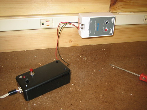
After a couple after-work evenings, the “DustBunny 3000” was born…

Hooked up to the “Powerflash” for testing…

Labeled and plugged into the volt meter showing ~4.74vdc on the output

And here’s the video demonstration of the system in action:


4 Responses to Custom Collector Controller